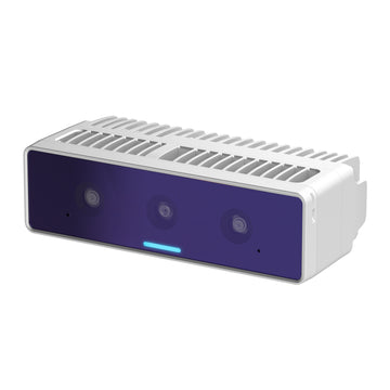
OAK4 D
Based on
Connection
USB 2/3 (up to 10 Gbps), Ethernet 2.5Gbps
Dot projector
No
Infrared
No
IMU
Yes
Sensor 1 - IMX586
Type
Color
DFOV / HFOV / VFOV
Size
1/2
Shutter
Rolling
Focus
Auto
Sensor 2, 3 - OV9282
Type
Monochrome
DFOV / HFOV / VFOV
Size
1/4
Shutter
Global
Focus
Fixed
Stereo
Wide FOV
Looking for more details? Visit specific features at Platform -> Features
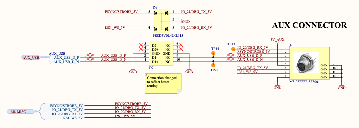
Connectors
M8 aux connector has 8pin female A-coded connector and the M12 ethernet has 8pin female X-coded connector. Cameras also include an M8 connector cap for waterproofing in case the M8 connector wouldn't be used.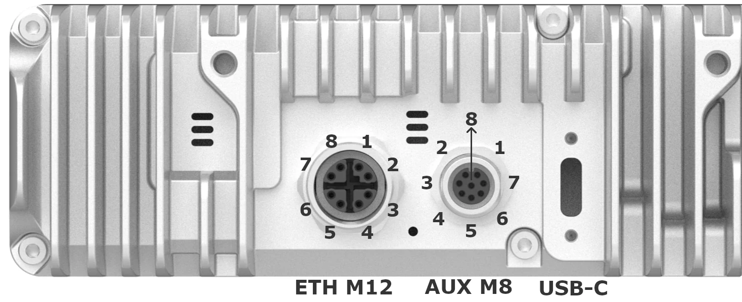
| Pin | M12 pin | M8 pin | M8 functionality |
|---|---|---|---|
| 1 | Eth MX0+ | GPIO_20/5V_RX | Either a 5V GPIO, or UART RX |
| 2 | Eth MX0- | FSYNC/STROBE_5V | FSYNC is the default, STROBE can be enabled |
| 3 | Eth MX1+ | USB D+ | USB 2.0 Host interface (Can't be used alongside USB-C interface) |
| 4 | Eth MX1- | USB D- | USB 2.0 Host interface (Can't be used alongside USB-C interface) |
| 5 | Eth MX3+ | 5V | This pin is used for sourcing 5V power (max 5W) to accessory devices connected to the M8 connector. |
| 6 | Eth MX3- | GPIO_21/5V_TX | Either a 5V GPIO, or UART TX |
| 7 | Eth MX2+ | DET_PIN | Used to detect what device is connected, can't be used for any other purpose |
| 8 | Eth MX2- | GND | Ground |
Power consumption
The RVC4 itself has a maximum power peaks of about 25W, which is mainly consumed by the SoC, Qualcomm's QCS8550, that is integrated inside the RVC4.- Max peak: 25W
- Max average: 10-15W
- Average idle: 1.6W
- Booting peak: 12W
- Booting average: 2.3W (~15sec)