Manual Calibration
Stereo camera recalibration
Estimate intrinsics and extrinsics of all camera sensors
ToF recalibration
Calibrate for ToF extrinsics
Auto-calibrate your camera
If you only need to calibrate extrinsics, you can do so dynamically by using our Dynamic Calibration Node.
About Camera Calibration
Intrinsic Parameters
- Focal Length (fx, fy): Sets the field of view. A higher focal length narrows the view, while a lower one widens it.
- Optical Center (cx, cy): The principal point where the optical axis intersects the sensor. A slight offset (around 20 pixels) is acceptable. This occurs due to minor lens-sensor alignment variations, like small shifts or tilts. Proper calibration compensates for these offsets, so they don't affect the camera's accuracy or performance.
- Distortion Coefficients: Adjust for lens imperfections:
- Radial Distortion (k1, k2, k3, k4, k5, k6): Corrects barrel or pincushion effects.
- Tangential Distortion (p1, p2): Compensates for lens-sensor misalignment.
- Thin Prism/Skew Distortion (s1, s2, s3, s4, τx, τy): Addresses tilt issues, particularly in wide-angle lenses.
Extrinsic Parameters
- Rotation: The orientation of the camera.
- Translation: The camera's position relative to a reference point.
Calibration Process
- Marker-Based Calibration: Using Charuco markers (a combination of chessboard and Aruco markers) positioned at various distances and angles for high accuracy.
- Controlled Environment: Performing calibration in a stable environment to cover all relevant poses and angles. This approach helps achieve consistently reproducible calibration results.
- Model-Specific Customization: Adapting the calibration process to the specific camera model for enhanced reliability.
Distortion Models
- Normal Field of View (NFOV):
Uses a standard perspective model to correct radial (k1, k2, k3, …) and tangential (p1, p2) distortions. - Wide Field of View (WFOV):
Utilizes an extended perspective model, which can have up to 14 total distortion parameters:- Radial Distortion: k1, k2, k3, k4, k5, k6
- Tangential Distortion: p1, p2
- Thin Prism: s1, s2, s3, s4
- Tilt Parameters: τx, τy
Note: In practice, we do not activate all 14 parameters. For wide-angle lenses, we enable two additional parameters (often τx and τy) to address the tilt we observe. This extended perspective model handles our wide-field-of-view (WFOV) lenses very well.
- Fisheye Lenses:
Employ a specialized model for extreme, circular distortions. We generally avoid fisheye calibration because OpenCV's fisheye support doesn't meet all our needs, and the extended perspective model already covers our WFOV applications effectively.
Stereo camera recalibration
All OAK cameras, except the Modular line, are calibrated before shipment, so recalibration is not required. For OAK FFC camera modules, camera calibration is required after mounting the cameras in the desired configuration.
./calibrate.py --help to print all available calibration options.Prerequisites
depthai repository on your computer, you need to clone it and install the requirements:Command Line
1git clone https://github.com/luxonis/depthai.git --branch main
2cd depthai
3git submodule update --init --recursive
4python3 install_requirements.py
Prepare Charuco Board
- 24" screen Charuco board
- 28" screen Charuco board
- 32" screen Charuco board
- 36" screen Charuco board
- 42" screen Charuco board
- 50" screen Charuco board
- 55" screen Charuco board
- 65" screen Charuco board
- 75" screen Charuco board
Display the Charuco Board
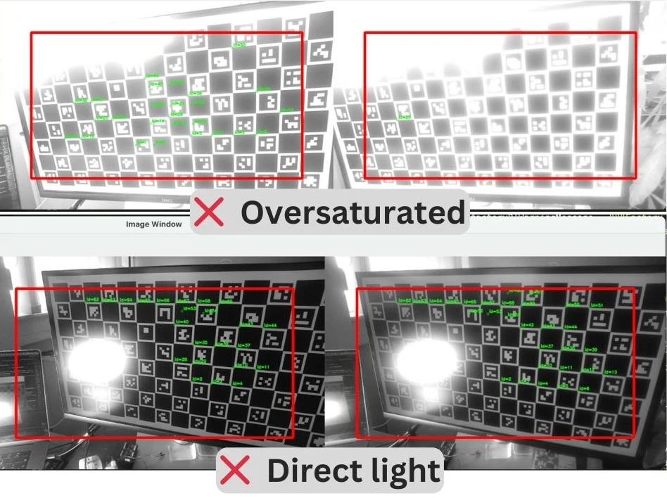
- Avoid too bright or dim screens.
- Avoid direct bright lights or sun on the screen.
- Display the Charuco board in full-screen.
SQUARE_SIZE_IN_CM argument for the calibration script.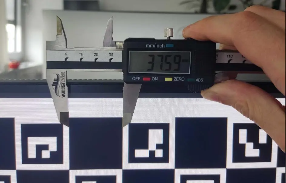
Calibration
| Argument | Argument alias | Argument Description |
|---|---|---|
-s | --squareSizeCm | Measured square size of the printed charuco board in centimeters |
-brd | --board | Name of the camera (from depthai-boards, not case-sensitive), or path to a custom .json board config |
-nx | --squaresX | Number of squares in X direction. SquaresX is specified in Prepare Charuco Board, depending on your screen size. |
-ny | --squaresY | Number of squares in Y direction. SquaresY is specified in Prepare Charuco Board, depending on your screen size. |
-cm | --cameraMode | Camera mode, either perspective (default) or fisheye. |
-mdmp | --minDetectedMarkersPercent | Minimum percentage of detected markers in a frame, to consider the frame valid. Default is 0.5 (50%). If you want to be more strict, you can increase this value, but it can cause longer time to get enough valid frames. |
-ep | --maxEpipolarError | Maximum epipolar error in pixels, to consider the frame valid. Default is 0.7. If you want to be more strict, you can decrease this value. |
Command Line
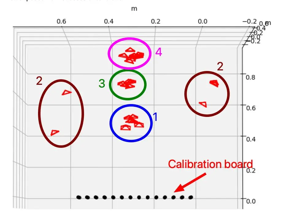
1python3 calibrate.py --helpCamera Positioning During Calibration
- Front view, with the calibration board in the middle of the FOV.
- Without moving the camera, rotate to align the camera FOV with the calibration board edges. Take 4 images, one for each edge of the screen.
- Front view, with the calibration board in the middle of the FOV.
- Similar to the close to the screen position, rotate the camera to align the FOV with the calibration board edges.
- Frontal view, with the calibration board in the middle of the FOV.
- Take 4 images aligning the camera FOV with all 4 edges, similar to the close and middle distance positions.
- Also, take 4 images aligning with the corners of the screen.
Running the Processing Stage
s key. The script shows epipolar lines for each image, and you should verify that they are aligned correctly. Once all images are checked, the calibration result, if successful, is flashed to the device EEPROM. Each captured image is saved in the dataset folder, so you can rerun the calibration process without capturing the images again.If you want to re-run the calibration process on the captured images, use the -m process argument:Command Line
1python3 calibrate.py -s [SQUARE_SIZE_IN_CM] --board [BOARD] -nx [squaresX] -ny [squaresY] -m processresources/ folder and can be used later for testing or debugging. You can also load or flash this local calibration file to the device. See the calibration load example for more details.Test Depth
Troubleshooting
- If calibration fails with error:
High reprojection error!, the usual cause is a misconfigured board config, often due to incorrect specified HFOV of the used camera module. - If despite successful calibration, the depth is still incorrect, perhaps your left and right cameras are swapped. Retry the calibration with changed board config, or swap the board sockets the cameras are plugged into.
ToF recalibration
Note that this calibration does not enhance the depth accuracy, as that aspect is managed by the device's firmware.
Calibration Procedure
Command Line
1git checkout new_tof_calib
2git submodule update --init --recursiveCommand Line
1python3 ./install_requirements.pycalibrate.py with the appropriate parameters for the Charuco board you are using. For example:Command Line
1python3 calibrate.py -db -nx 12 -ny 9 -c 1 -cd 0 -s 6 -ms 4.7 -brd OAK-D-SR-POE-db: Indicates the default board, meaning you are using Charuco markers.-nx: Number of Charuco markers in the x direction.-ny: Number of Charuco markers in the y direction.-c: Number of pictures taken each time the polygon is displayed (optional).-cd: Countdown time before a picture is taken in seconds (optional).-s: Size of the square around the Charuco marker in centimeters.-ms: Size of the markers in centimeters.-brd: Board of the device (in this case, OAK-D-SR-POE).
division by zero or Failed to detect markers in the image dataset/rgb/rgb_p3_10.png, delete the image with poor Charuco board detection from all camera folders, then run the same command again with the added -m process parameter. This starts only the processing stage, so you do not have to retake the board images.Command Line
1python3 calibrate.py -db -nx 12 -ny 9 -c 1 -cd 0 -s 6 -ms 4.7 -brd OAK-D-SR-POE -m process