This guide serves as an introduction on how one can integrate DepthAI (Spatial AI platform) into their own custom products. When designing the PCB, please also see OAK Design Guide and Mechanical Considerations.
Difficulty of integrating DepthAI into products
When designing the DepthAI platform we always made efforts to consider long term integration needs, with the goal of making it as simple as possible to integrate into other products.
What is the OAK System on Module (SoM)?
RVC2
RVC3
RVC2
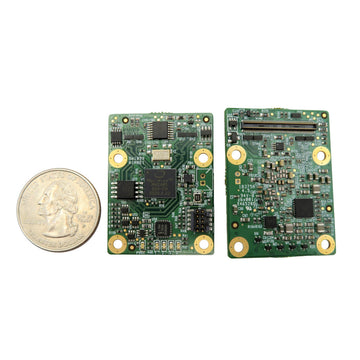
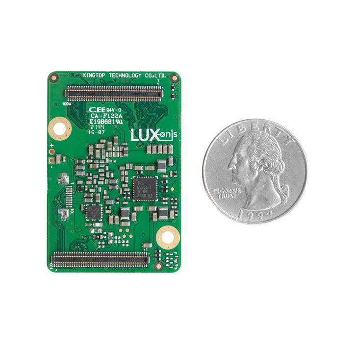
The OAK SoM is a small form-factor PCB that features a powerful RVC2. The RVC2 has 16 powerful SHAVE cores and also features the Neural Compute Engine, which is a dedicated hardware accelerator for deep neural network inference. In addition, OAK-SoM-Pro has NOR Flash, which can be used as an alternative to the USB boot. The idea of SoM is that customer can use it to build their own device, since SoM is a very complex, 12 layer PCB. That way our SoM devices serve as an abstraction layer. They can also be used in standalone mode without a host computer, although not all devices support that use-case.We have 2 types of RVC2 SoM devices:
NOR flash capability, OAK-SoM does not have NOR flash by default, while the Pro has 1Gbit NOR flash by default (in some iterations 125Mbit is used),
This allows the Pro to be used in standalone mode without a host computer, while the OAK-SoM requires a host computer to boot from USB. The Pro also supports Ethernet and SD card functionality (mutually exclusive).
Baseboards
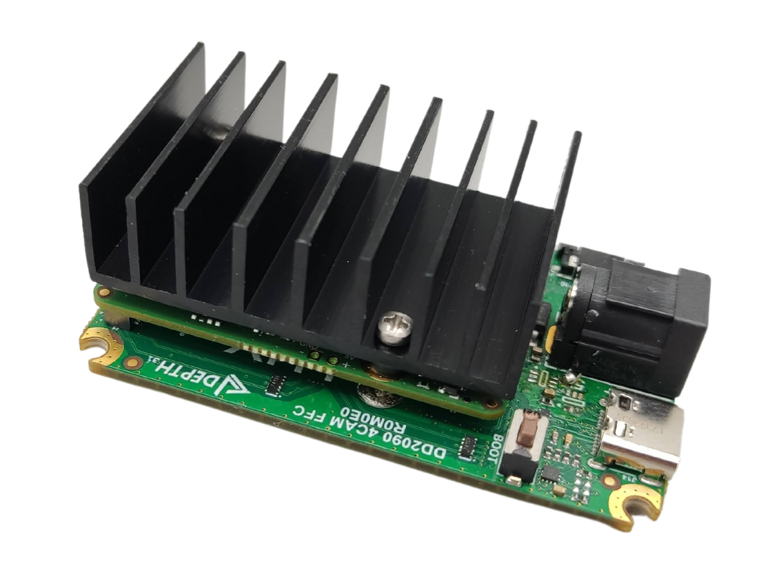
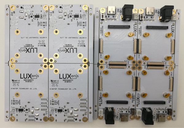
Just like our software and our library, our hardware is opensource too. That way it is not just a black box. It allows you to see how our devices (PCB) are designed and change them however you like. Even high-school students were able to design their own baseboard by modifying existing opensource designs. Most of the complexity is on the SoM, so the baseboard can be a 2-layer PCB.Here is an example of a baseboard without the SoM:And here is an example of a SoM on the baseboard - OAK-FFC 4P:
NOR Flash and Powering
The OAK-SoM-IoT and OAK-SoM-Pro have the QSPI NOR Flash, which is capable of quick random access location and is used to store and run code. This is the key factor to support the standalone use case.Power consumption can vary depending on the application. A stereo vision application running Mobilenet-SSD V2 at 30 FPS typically consumes about 2.5 W, but more computationally heavy applications can consume up to 5 W. Most of this power is consumed by the RVC2.For more information, see the respective datasheet on our GitHub hardware repository OAK-SoM Datasheet.
OAK Design Guide and Mechanical Considerations
Start with the why:
OAK models that derive depth information from a stereo pair (or stereo pairs) of cameras do so by feature-matching and triangulation. The feature matching happens by comparing the features acquired on each row from one camera to the features acquired on the second camera in the same row.To achieve this, the cameras must be calibrated such that the horizontal lines from one camera can perfectly align with those of the other camera in the stereo pair.This calibration involves:
The intrinsics of the left camera.
The intrinsics of the right camera.
The extrinsics of the translation and rotation between the left and right cameras.
Rectification parameters to align the rows of the stereo camera.
The intrinsics matrix contains the estimation of focal length and optical centers of each camera, crucial for obtaining accurate depth calculations in a stereo setup. Extrinsic calibration provides the relative position of the cameras, while rectification ensures alignment of the stereo images for feature matching.For high-quality depth results, these parameters must remain stable over time, necessitating rigid physical properties of the camera modules and their mounting to prevent unintended movement or rotation.
Move to the how:
Ensure the camera assembly is rigid and free from mechanical stress, load, or torque.
Consider mounting points and cable entry points to minimize motion and pressure that could deform the cameras.
Share designs early with Luxonis for feedback on mechanical robustness.
Move to the what:
Mount cameras on rigid structures:
Reinforce PCB mounts with nearby metal supports to prevent bending.
Use thermally isolated metals for mounting to avoid thermal expansion affecting camera alignment.
Design external entry points to prevent forces from causing camera rotation or translation.
Use securely screwed M12/C/CS-mount cameras; employ nylon threading to prevent loosening due to vibration.
Secure compact camera modules (CCM) with a combination of pressure-sensitive adhesive (PSA) and rigid glue to prevent detachment from flexible flat cables (FFC).
 And here is an example of a SoM on the baseboard - OAK-FFC 4P: