- CameraSocket coordinate systems — defined by the camera pinhole model during calibration.
- Housing coordinate systems — defined from the mechanical shape of the device.
Notation
CameraSocket coordinate systems
Socket to camera mapping
| Socket Number | Socket Name | Camera Name |
|---|---|---|
| 0 | CAM_A | RGB |
| 1 | CAM_B | LEFT |
| 2 | CAM_C | RIGHT |
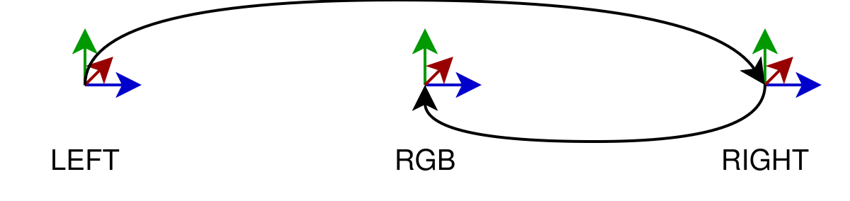
Origin (reference) camera
CAM_A, CAM_B, and CAM_C, the origin is CAM_A.Each image produced by DepthAI also carries its own ImgTransformation, which includes the camera extrinsics — the transformation from the virtual camera to the origin (typically CAM_A as defined above).A virtual camera is the camera model that describes the image as it currently exists — after any processing (warp, crop, undistort, etc.) has been applied. When DepthAI transforms an image, the result is equivalent to a photo taken by a different, virtual camera that may be positioned and oriented slightly differently in space. Because of this, the virtual camera's extrinsics can differ from the physical sensor's extrinsics that were established during calibration. ImgTransformation always reflects the virtual camera so that downstream nodes work with up-to-date geometry.Camera-to-camera transforms
Python
1# srcCamera / dstCamera — any dai.CameraBoardSocket value:
2#   CAM_A, CAM_B, CAM_C, CAM_D, CAM_E, CAM_F, CAM_G, CAM_H, CAM_I, CAM_J
3
4# Get 4x4 extrinsic transformation matrix from CAM_B to CAM_A
5calibration.getCameraExtrinsics(dai.CameraBoardSocket.CAM_B, dai.CameraBoardSocket.CAM_A)srcCamera to dstCamera:Internally, DepthAI computes this by chaining two origin transforms:Python
1calibration.getExtrinsicsToOrigin(srcCamera)  # returns T^src_origin
2calibration.getExtrinsicsToOrigin(dstCamera)  # returns T^dst_origin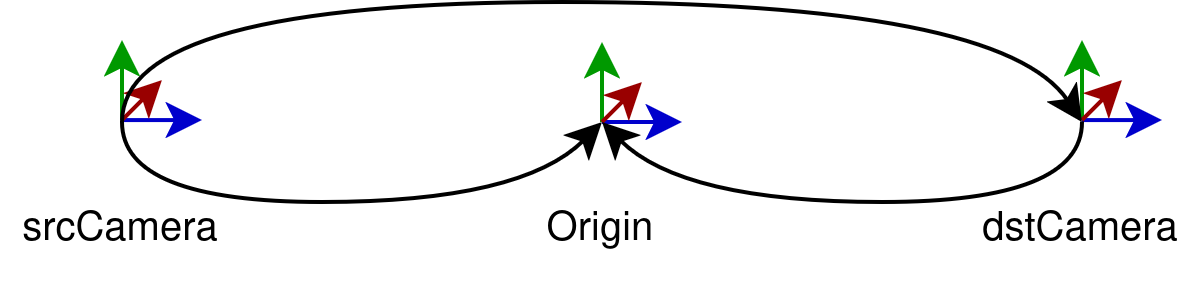
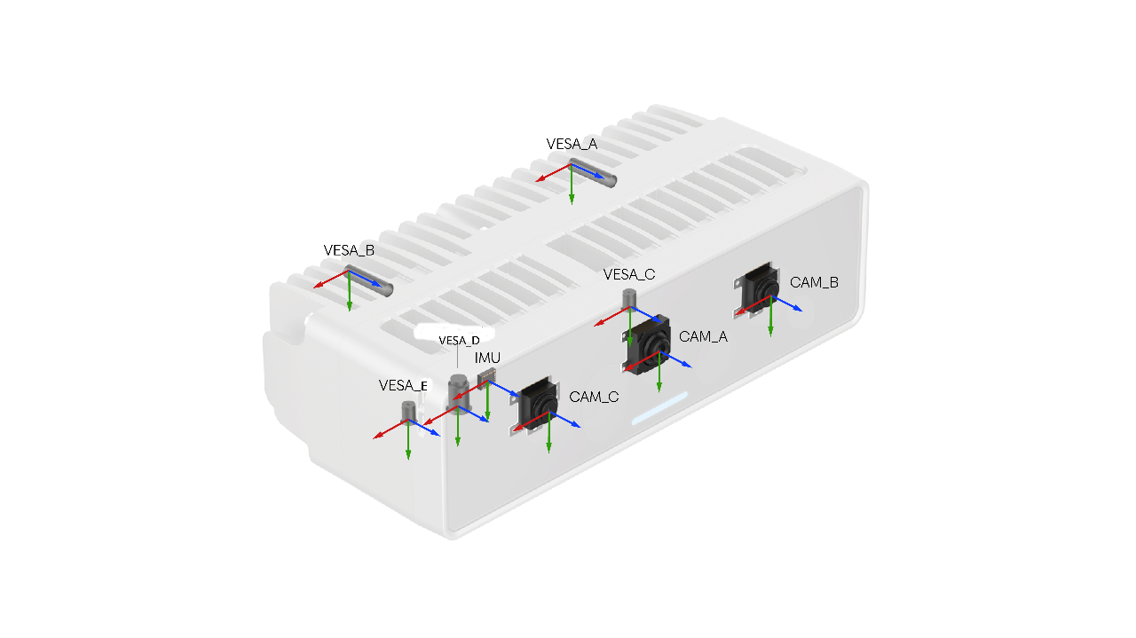
Housing coordinate systems
VESA_A–VESA_J— Device mounting points.FRONT_CAM_A–FRONT_CAM_J— Positioned at the front glass, aligned with the front glass plane.CAM_A–CAM_J— Positioned at camera sensor spec locations.
Transforming to a housing coordinate system
Python
1# housingCS — any dai.HousingCoordinateSystem value:
2#   CAM_A … CAM_J           — camera housing origin
3#   FRONT_CAM_A … FRONT_CAM_J — front-cover coordinate system per camera
4#   VESA_A … VESA_J         — VESA mount coordinate system per camera
5#   IMU                     — IMU housing origin
6
7# Get 4x4 transform from CAM_A into the VESA_A housing coordinate system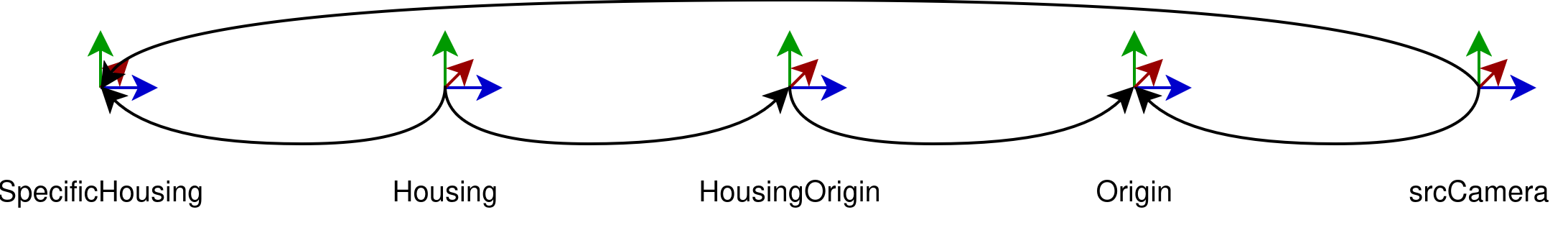
8calibration.getHousingCalibration(dai.CameraBoardSocket.CAM_A, dai.HousingCoordinateSystem.VESA_A)srcCamera to the selected housing coordinate system:Internally, this involves three steps:Compute the housing-to-origin chain
Python
1calibration.getHousingToHousingOrigin()       # returns T^housing_housingOrigin
2calibration.getExtrinsicsToOrigin(housingOrigin)  # returns T^housingOrigin_origin
3calibration.getExtrinsicsToOrigin(srcCamera)      # returns T^srcCamera_origin
Retrieve the housing-to-specific-housing transform
The housing-to-specific-housing transform is retrieved from the DepthAI Boards JSON file:
Compose the final transform
ImageTransformation — working with data
ImgTransformation as the source of transformations. Every data frame carries its own extrinsics — the transformation from the data frame to the origin (ref) camera. This extrinsic is kept up to date automatically when:- An operation is performed on the data (crop, resize, undistort, etc.)
- The calibration changes at runtime (e.g. due to the AutoCalibration node)
ImgTransformation automatically, so they stay calibration-aware without manual intervention.Need assistance?
Head over to Discussion Forum for technical support or any other questions you might have.