IMU
IMU
- sensors used across platforms
- supported output families
- IMU-to-camera alignment
- factory calibration
- noise characterization
All Kickstarter-backed OAK-D-Lite cameras do not have an onboard IMU.
IMU models
BNO08X family
9-axis sensor hub used on RVC2 devices, including raw and fused orientation outputs.
BMI270
6-axis accelerometer + gyroscope IMU used on RVC2 platforms as a raw inertial sensor path.
LSM6DSV
6-axis RVC4 IMU with accelerometer, gyroscope, and internal derived outputs.
AK09919
3-axis RVC4 companion magnetometer used when magnetic reference is needed.
Capability overview
| Sensor | Axes | Physical sensors | Magnetometer | Sensor-side derived outputs | Absolute heading on-sensor |
|---|---|---|---|---|---|
| BNO08X | 9 | Accelerometer, gyroscope, magnetometer | Yes | Rotation vector, game rotation vector, geomagnetic rotation vector, gravity, linear acceleration | Yes |
| BMI270 | 6 | Accelerometer, gyroscope | No | None exposed as sensor-side fused orientation outputs | No |
| LSM6DSV | 6 | Accelerometer, gyroscope | No | Game rotation vector, gravity vector, gyroscope bias | No |
| AK09919 | 3 | Magnetometer | Yes | None | No |
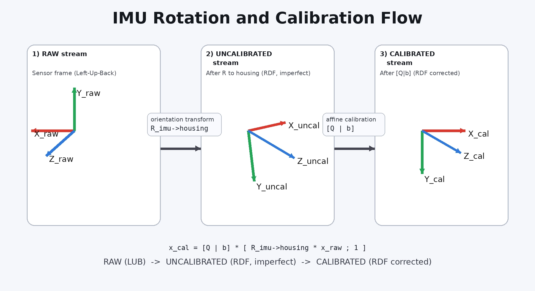
Output types
Raw
Uncalibrated
- +X right
- +Y down
- +Z forward
Calibrated
- frame rotation into the Luxonis RDF coordinate system
- factory intrinsic calibration terms
- compensation for deterministic sensor errors such as bias, scale error, shear / cross-axis terms, and assembly-related imperfections including small mounting or soldering deviations between the IMU and PCB
Sensor-provided derived outputs
- gravity vector
- linear acceleration / gravity-compensated acceleration
- rotation vector / quaternion outputs
IMU reference frames
imuExtrinsics
imuExtrinsics is the rigid transform between the IMU frame and a camera frame.In practice:- for vectors such as acceleration and angular velocity, the rotation part of the transform is used
- for full multi-sensor geometry, the full 4x4 transform is used
imuExtrinsics.Factory IMU calibration
- bias
- scale factor error
- cross-axis / shear terms
- assembly-related alignment imperfections
imuExtrinsics: intrinsic IMU calibration corrects the sensor itself, while extrinsic calibration relates the IMU frame to the camera frame.Noise characterization
- VIO
- EKF / UKF pipelines
- SLAM
- simulation
- covariance tuning
- tools such as Kalibr
| Concept | Common IMU / Allan term | Kalibr name | Luxonis documentation name |
|---|---|---|---|
| Accelerometer white noise | VRW | accelerometer_noise_density | accel_noise_density |
| Accelerometer bias drift | Bias random walk | accelerometer_random_walk | accel_bias_random_walk |
| Accelerometer bias stability | Bias instability | - | accel_bias_instability |
| Gyroscope white noise | ARW | gyroscope_noise_density | gyro_noise_density |
| Gyroscope bias drift | RRW / bias random walk | gyroscope_random_walk | gyro_bias_random_walk |
| Gyroscope bias stability | Bias instability | - | gyro_bias_instability |