StereoDepth
How to place it
Python
C++
Python
Python
1pipeline = dai.Pipeline()
2stereo = pipeline.create(dai.node.StereoDepth)
Inputs and Outputs
debugDispLrCheckIt1, debugDispLrCheckIt2, debugExtDispLrCheckIt1, debugExtDispLrCheckIt2, debugDispCostDump and confidenceMap.Internal block diagram of StereoDepth node
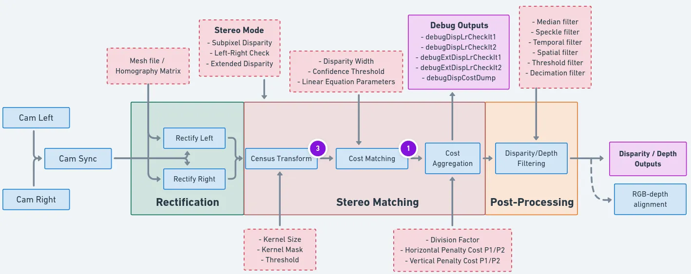 On the diagram, red rectangle are firmware settings that are configurable via the API. Gray rectangles are settings that that are not yet exposed to the API. We plan on exposing as much configurability as possible, but please inform us if you would like to see these settings configurable sooner.If you click on the image, you will be redirected to the webapp. Some blocks have notes that provide additional technical information.
Currently configurable blocks
- Stereo Mode:
- Left-Right Check:
- Left-Right Check or LR-Check is used to remove incorrectly calculated disparity pixels due to occlusions at object borders (Left and Right camera views are slightly different).
- Computes disparity by matching in R->L direction.
- Computes disparity by matching in L->R direction.
- Combines results from steps 1 and 2, running on Shave: each pixel d = disparity_LR(x,y) is compared with disparity_RL(x-d,y). If the difference is above a threshold, the pixel at (x,y) in the final disparity map is invalidated.
- You can use
debugDispLrCheckIt1anddebugDispLrCheckIt2debug outputs for debugging/fine-tuning purposes.
- Left-Right Check or LR-Check is used to remove incorrectly calculated disparity pixels due to occlusions at object borders (Left and Right camera views are slightly different).
- Extended Disparity:
- Extended disparity mode allows detecting closer distance objects for the given baseline. This increases the maximum disparity search from 96 to 191, meaning the range is now: [0..190].
- Computes disparity on the original size images (e.g. 1280x720).
- Computes disparity on 2x downscaled images (e.g. 640x360).
- Combines the two level disparities on Shave, effectively covering a total disparity range of 191 pixels (in relation to the original resolution).
- You can use
debugExtDispLrCheckIt1anddebugExtDispLrCheckIt2debug outputs for debugging/fine-tuning purposes.
- Extended disparity mode allows detecting closer distance objects for the given baseline. This increases the maximum disparity search from 96 to 191, meaning the range is now: [0..190].
- Subpixel Disparity:
- Subpixel mode improves the precision and is especially useful for long-range measurements. It also helps for better estimating surface normals.
- In this mode, stereo cameras perform: 94 depth steps * 8 subpixel depth steps + 2 (min/max values) = 754 depth steps.
- For comparison of normal disparity vs. subpixel disparity images, click here.
- Left-Right Check:
- Depth Filters:
- Depth Filtering / Depth Post-Processing is performed at the end of the depth pipeline. It helps with noise reduction and overall depth quality.
- Mesh files:
- Mesh files (homography matrix) are generated using the camera intrinsics, distortion coeffs, and rectification rotations. These files help in overcoming the distortions in the camera increasing the accuracy and also help in when wide FOV lens are used.
- Currently, mesh files are generated only for stereo cameras on the host during calibration. The generated mesh files are stored in depthai/resources which users can load to the device. This process will be moved to on device in the upcoming releases.
- Confidence Threshold:
- Confidence threshold: Stereo depth algorithm searches for the matching feature from the right camera point to the left image (along the 96 disparity levels). During this process, it computes the cost for each disparity level and chooses the minimal cost between two disparities and uses it to compute the confidence at each pixel. Stereo node will output disparity/depth pixels only where depth confidence is below the confidence threshold (lower the confidence value means better depth accuracy).
- LR check threshold: Disparity is considered for the output when the difference between LR and RL disparities is smaller than the LR check threshold.
Limitations
- Median filtering is disabled when subpixel mode is set to 4 or 5 bits.
- For RGB-depth alignment the RGB camera has to be placed on the same horizontal line as the stereo camera pair.
- RGB-depth alignment doesn't work when using disparity shift.
Changing camera calibration during runtime
device.setCalibration() method and can be used if device stereo quality degrades over time due to environmental factors. The same data can be obtained using the device.getCalibration().Depth Presets
Depth Presets
| Feature | Default | Face | High Detail | Robotics |
|---|---|---|---|---|
| Base Profile | HIGH_DENSITY | HIGH_DENSITY | HIGH_ACCURACY | HIGH_DENSITY |
| Median Filter | 7x7 kernel | Off | Off | 7x7 kernel |
| Subpixel Precision | 3-bit | 5-bit | 5-bit | 3-bit |
| Extended Disparity | No | Yes | Yes | No |
| Range | 0-15m | 3cm-3m | 0-15m | 0-10m |
| Temporal Filter | Enabled | Enabled | Enabled | Disabled |
| Use Case | General purpose | Face tracking, biometrics | 3D scanning, object details | Navigation, obstacle detection |
- Left-right consistency check
- 2x decimation with pixel skipping
- Speckle filtering (range: 200, threshold: 2)
- 3 hardware resources for post-processing
Stereo depth FPS
| Process \ Resolution | 400P [ms] | 720P [ms] | 800P [ms] |
|---|---|---|---|
| Rectification | 1.5 | 5 | 6 |
| Wide FOV rectification | 2.5 | 8 | 9 |
- LR: Left-Right check (
stereo.setLeftRightCheck()). It requires 2 stereo matching operations (L->R and R->L direction) and then a combines results - Ext: Extended disparity mode (
stereo.setExtendedDisparity()). It requires 2 stereo matching operations (original and downscaled) and then combines results - Sub: Subpixel matching (
stereo.setSubpixel()). For each pixel you get 96 bytes for cost map (one byte for each disparity level), so for 800P frame about 98MB of data needs to get moved to CMX memory (used by SHAVEs) for subpixel calculation. So bottleneck in this case is memory bandwidth (~4.1GB/sec). Number of subpixel bits doesn't affect latency
| Process \ Resolution | 400P [ms] | 720P [ms] | 800P [ms] |
|---|---|---|---|
| No LR, No Ext, No Sub | 3.4 | 7.4 | 8.1 |
| No LR, No Ext, Sub | 6.2 | 21.7 | 23.9 |
| No LR, Ext, No Sub | 8.5 | 21.5 | 23.5 |
| No LR, Ext, Sub | 11 | 32.7 | 36.7 |
| LR, No Ext, No Sub | 7.4 | 18 | 19.8 |
| LR, No Ext, Sub | 10.1 | 27.6 | 30.5 |
| LR, Ext, No Sub | 16.7 | 43.7 | 48.3 |
| LR, Ext, Sub | 20.4 | 56 | 62 |
3x3, 5x5, 7x7) doesn't affect the latency:| Process \ Resolution | 400P [ms] | 720P [ms] | 800P [ms] |
|---|---|---|---|
Median filtering (3x3 / 5x5 / 7x7) | 0.8 | 1.8 | 1.8 |
Usage
Python
C++
Python
Python
1pipeline = dai.Pipeline()
2stereo = pipeline.create(dai.node.StereoDepth)
3
4# Better handling for occlusions:
5stereo.setLeftRightCheck(False)
6# Closer-in minimum depth, disparity range is doubled:
7stereo.setExtendedDisparity(False)
8# Better accuracy for longer distance, fractional disparity 32-levels:
9stereo.setSubpixel(False)
10
11# Define and configure MonoCamera nodes beforehand
12left.out.link(stereo.left)
13right.out.link(stereo.right)
Examples of functionality
- Depth Preview
- RGB Depth alignment - align depth map to color camera (RGB-D)
- Stereo Depth Post-Processing filters
- Mono & MobilenetSSD & Depth
- RGB & MobilenetSSD with spatial data
Reference
class
depthai.node.StereoDepth(depthai.Node)
class
PresetMode
Preset modes for stereo depth. Members: HIGH_ACCURACY : **Deprecated:** Will be removed in future releases and replaced with DEFAULT HIGH_DENSITY : **Deprecated:** Will be removed in future releases and replaced with DEFAULT DEFAULT FACE HIGH_DETAIL ROBOTICS
method
enableDistortionCorrection(self, arg0: bool)Equivalent to useHomographyRectification(!enableDistortionCorrection)
method
getMaxDisparity(self) -> float: floatUseful for normalization of the disparity map. Returns: Maximum disparity value that the node can return
method
loadMeshData(self, dataLeft: collections.abc.Sequence

[


typing.SupportsInt

], dataRight: collections.abc.Sequence

[


typing.SupportsInt

])
Specify mesh calibration data for 'left' and 'right' inputs, as vectors of bytes. Overrides useHomographyRectification behavior. See `loadMeshFiles` for the expected data format
method
loadMeshFiles(self, pathLeft: Path, pathRight: Path)Specify local filesystem paths to the mesh calibration files for 'left' and 'right' inputs. When a mesh calibration is set, it overrides the camera intrinsics/extrinsics matrices. Overrides useHomographyRectification behavior. Mesh format: a sequence of (y,x) points as 'float' with coordinates from the input image to be mapped in the output. The mesh can be subsampled, configured by `setMeshStep`. With a 1280x800 resolution and the default (16,16) step, the required mesh size is: width: 1280 / 16 + 1 = 81 height: 800 / 16 + 1 = 51
method
setAlphaScaling(self, arg0: typing.SupportsFloat)Free scaling parameter between 0 (when all the pixels in the undistorted image are valid) and 1 (when all the source image pixels are retained in the undistorted image). On some high distortion lenses, and/or due to rectification (image rotated) invalid areas may appear even with alpha=0, in these cases alpha < 0.0 helps removing invalid areas. See getOptimalNewCameraMatrix from opencv for more details.
method
setBaseline(self, arg0: typing.SupportsFloat)Override baseline from calibration. Used only in disparity to depth conversion. Units are centimeters.
method
setConfidenceThreshold(self, arg0: typing.SupportsInt)Confidence threshold for disparity calculation Parameter ``confThr``: Confidence threshold value 0..255
method
setDefaultProfilePreset(self, arg0: StereoDepth.PresetMode)Sets a default preset based on specified option. Parameter ``mode``: Stereo depth preset mode
method
method
setDepthAlignmentUseSpecTranslation(self, arg0: bool)Use baseline information for depth alignment from specs (design data) or from calibration. Default: true
method
setDisparityToDepthUseSpecTranslation(self, arg0: bool)Use baseline information for disparity to depth conversion from specs (design data) or from calibration. Default: true
method
setEmptyCalibration(self)Specify that a passthrough/dummy calibration should be used, when input frames are already rectified (e.g. sourced from recordings on the host)
method
setExtendedDisparity(self, enable: bool)Disparity range increased from 0-95 to 0-190, combined from full resolution and downscaled images. Suitable for short range objects. Currently incompatible with sub-pixel disparity
method
setFocalLength(self, arg0: typing.SupportsFloat)Override focal length from calibration. Used only in disparity to depth conversion. Units are pixels.
method
setFocalLengthFromCalibration(self, arg0: bool)Whether to use focal length from calibration intrinsics or calculate based on calibration FOV. Default value is true.
method
method
setLeftRightCheck(self, enable: bool)Computes and combines disparities in both L-R and R-L directions, and combine them. For better occlusion handling, discarding invalid disparity values
method
setMedianFilter(self, arg0: depthai.MedianFilter)Parameter ``median``: Set kernel size for disparity/depth median filtering, or disable
method
setMeshStep(self, width: typing.SupportsInt, height: typing.SupportsInt)Set the distance between mesh points. Default: (16, 16)
method
setNumFramesPool(self, arg0: typing.SupportsInt)Specify number of frames in pool. Parameter ``numFramesPool``: How many frames should the pool have
method
method
setOutputKeepAspectRatio(self, keep: bool)Specifies whether the frames resized by `setOutputSize` should preserve aspect ratio, with potential cropping when enabled. Default `true`
method
method
setOutputSize(self, width: typing.SupportsInt, height: typing.SupportsInt)Specify disparity/depth output resolution size, implemented by scaling. Currently only applicable when aligning to RGB camera
method
setPostProcessingHardwareResources(self, arg0: typing.SupportsInt, arg1: typing.SupportsInt)Specify allocated hardware resources for stereo depth. Suitable only to increase post processing runtime. Parameter ``numShaves``: Number of shaves. Parameter ``numMemorySlices``: Number of memory slices.
method
setRectification(self, enable: bool)Rectify input images or not.
method
setRectificationUseSpecTranslation(self, arg0: bool)Obtain rectification matrices using spec translation (design data) or from calibration in calculations. Should be used only for debugging. Default: false
method
setRectifyEdgeFillColor(self, color: typing.SupportsInt)Fill color for missing data at frame edges Parameter ``color``: Grayscale 0..255, or -1 to replicate pixels
method
setRectifyMirrorFrame(self, arg0: bool)DEPRECATED function. It was removed, since rectified images are not flipped anymore. Mirror rectified frames, only when LR-check mode is disabled. Default `true`. The mirroring is required to have a normal non-mirrored disparity/depth output. A side effect of this option is disparity alignment to the perspective of left or right input: `false`: mapped to left and mirrored, `true`: mapped to right. With LR-check enabled, this option is ignored, none of the outputs are mirrored, and disparity is mapped to right. Parameter ``enable``: True for normal disparity/depth, otherwise mirrored
method
setRuntimeModeSwitch(self, arg0: bool)Enable runtime stereo mode switch, e.g. from standard to LR-check. Note: when enabled resources allocated for worst case to enable switching to any mode.
method
setSubpixel(self, enable: bool)Computes disparity with sub-pixel interpolation (3 fractional bits by default). Suitable for long range. Currently incompatible with extended disparity
method
setSubpixelFractionalBits(self, subpixelFractionalBits: typing.SupportsInt)Number of fractional bits for subpixel mode. Default value: 3. Valid values: 3,4,5. Defines the number of fractional disparities: 2^x. Median filter postprocessing is supported only for 3 fractional bits.
method
useHomographyRectification(self, arg0: bool)Use 3x3 homography matrix for stereo rectification instead of sparse mesh generated on device. Default behaviour is AUTO, for lenses with FOV over 85 degrees sparse mesh is used, otherwise 3x3 homography. If custom mesh data is provided through loadMeshData or loadMeshFiles this option is ignored. Parameter ``useHomographyRectification``: true: 3x3 homography matrix generated from calibration data is used for stereo rectification, can't correct lens distortion. false: sparse mesh is generated on-device from calibration data with mesh step specified with setMeshStep (Default: (16, 16)), can correct lens distortion. Implementation for generating the mesh is same as opencv's initUndistortRectifyMap function. Only the first 8 distortion coefficients are used from calibration data.
property
confidenceMap
Outputs ImgFrame message that carries RAW8 confidence map. Lower values means higher confidence of the calculated disparity value. RGB alignment, left-right check or any postproccessing (e.g. median filter) is not performed on confidence map.
property
debugDispCostDump
Outputs ImgFrame message that carries cost dump of disparity map. Useful for debugging/fine tuning.
property
debugDispLrCheckIt1
Outputs ImgFrame message that carries left-right check first iteration (before combining with second iteration) disparity map. Useful for debugging/fine tuning.
property
debugDispLrCheckIt2
Outputs ImgFrame message that carries left-right check second iteration (before combining with first iteration) disparity map. Useful for debugging/fine tuning.
property
debugExtDispLrCheckIt1
Outputs ImgFrame message that carries extended left-right check first iteration (downscaled frame, before combining with second iteration) disparity map. Useful for debugging/fine tuning.
property
debugExtDispLrCheckIt2
Outputs ImgFrame message that carries extended left-right check second iteration (downscaled frame, before combining with first iteration) disparity map. Useful for debugging/fine tuning.
property
depth
Outputs ImgFrame message that carries RAW16 encoded (0..65535) depth data in depth units (millimeter by default). Non-determined / invalid depth values are set to 0
property
disparity
Outputs ImgFrame message that carries RAW8 / RAW16 encoded disparity data: RAW8 encoded (0..95) for standard mode; RAW8 encoded (0..190) for extended disparity mode; RAW16 encoded for subpixel disparity mode: - 0..760 for 3 fractional bits (by default) - 0..1520 for 4 fractional bits - 0..3040 for 5 fractional bits
property
initialConfig
Initial config to use for StereoDepth.
property
inputConfig
Input StereoDepthConfig message with ability to modify parameters in runtime. Default queue is non-blocking with size 4.
property
left
Input for left ImgFrame of left-right pair Default queue is non-blocking with size 8
property
outConfig
Outputs StereoDepthConfig message that contains current stereo configuration.
property
rectifiedLeft
Outputs ImgFrame message that carries RAW8 encoded (grayscale) rectified frame data.
property
rectifiedRight
Outputs ImgFrame message that carries RAW8 encoded (grayscale) rectified frame data.
property
right
Input for right ImgFrame of left-right pair Default queue is non-blocking with size 8
property
syncedLeft
Passthrough ImgFrame message from 'left' Input.
property
syncedRight
Passthrough ImgFrame message from 'right' Input.
class
depthai.node.StereoDepth.PresetMode
variable
variable
variable
variable
variable
variable
variable
method
method
method
method
method
method
method
method
method
method
property
property
Disparity
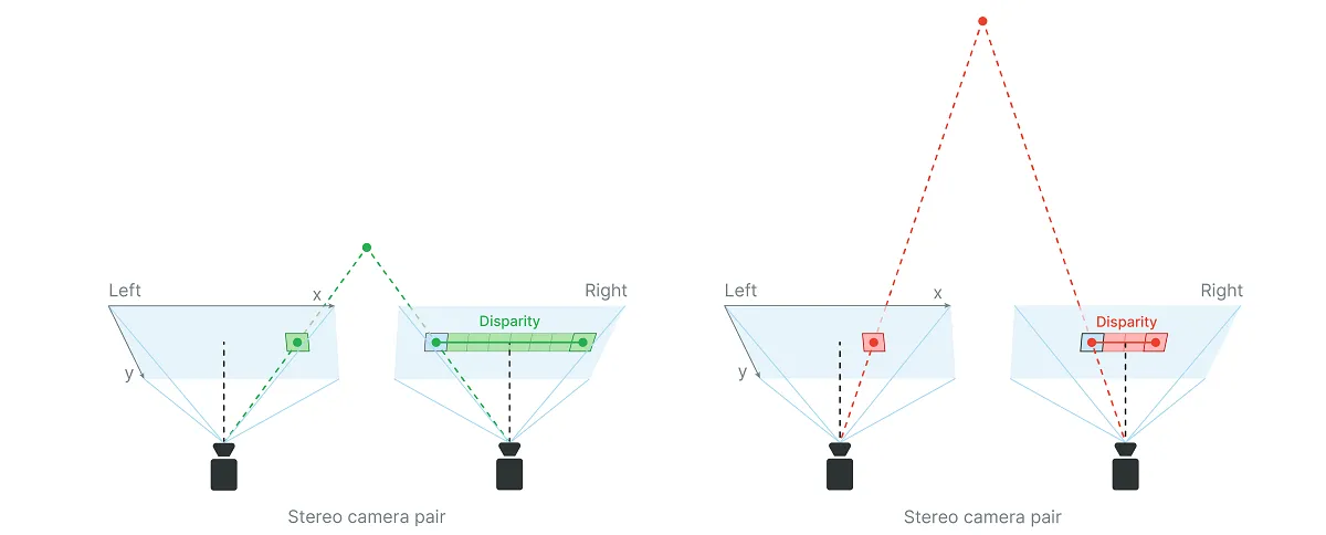 When calculating the disparity, each pixel in the disparity map gets assigned a confidence value
 0..255 by the stereo matching algorithm, as:0- maximum confidence that it holds a valid value255- minimum confidence, so there is more chance that the value is incorrect
stereo.initialConfig.setConfidenceThreshold().Calculate depth using disparity map
Python
1depth = focal_length_in_pixels * baseline / disparity_in_pixelsintrinsics[0][0]):Python
1import depthai as dai
2
3with dai.Device() as device:
4  calibData = device.readCalibration()
5  intrinsics = calibData.getCameraIntrinsics(dai.CameraBoardSocket.CAM_C)
6 print('Right mono camera focal length in pixels:', intrinsics[0][0])Python
1focal_length_in_pixels = image_width_in_pixels * 0.5 / tan(HFOV * 0.5 * PI/180)
2
3# With 400P mono camera resolution where HFOV=71.9 degrees
4focal_length_in_pixels = 640 * 0.5 / tan(71.9 * 0.5 * PI / 180) = 441.25
5
6# With 800P mono camera resolution where HFOV=71.9 degrees
7focal_length_in_pixels = 1280 * 0.5 / tan(71.9 * 0.5 * PI / 180) = 882.5Python
1# For OAK-D @ 400P mono cameras and disparity of eg. 50 pixels
2depth = 441.25 * 7.5 / 50 = 66.19 # cm
3
4# For OAK-D @ 800P mono cameras and disparity of eg. 10 pixels
5depth = 882.5 * 7.5 / 10 = 661.88 # cmuint16, where 0 is a special value, meaning that distance is unknown.Min stereo depth distance
Python
1min_distance = focal_length_in_pixels * baseline / disparity_in_pixels = 882.5 * 7.5cm / 95 = 69.67cm- Changing the resolution to 640x400, instead of the standard 1280x800.
- Enabling Extended Disparity.
Python
1min_distance = focal_length_in_pixels * baseline / disparity_in_pixels = 882.5 * 7.5cm / 190 = 34.84cmApplying both of those options is possible, which would set the minimum depth to 1/4 of the standard settings, but at such short distances the minimum depth is limited by focal length, which is 19.6cm, since OAK-D mono cameras have fixed focus distance: 19.6cm - infinity.
Disparity shift to lower min depth perception
 Left graph shows min and max disparity and depth for OAK-D (7.5cm baseline, 800P resolution, ~70° HFOV) by default (disparity shift=0). See Calculate depth using disparity map. Since hardware (stereo block) has a fixed 95 pixel disparity search, DepthAI will search from 0 pixels (depth=INF) to 95 pixels (depth=71cm).Right graph shows the same, but at disparity shift set to 30 pixels. This means that disparity search will be from 30 pixels (depth=2.2m) to 125 pixels (depth=50cm). This also means that depth will be very accurate at the short range (theoretically below 5mm depth error).Limitations:
- Because of the inverse relationship between disparity and depth, MaxZ will decrease much faster than MinZ as the disparity shift is increased. Therefore, it is advised not to use a larger than necessary disparity shift.
- Tradeoff in reducing the MinZ this way is that objects at distances farther away than MaxZ will not be seen.
- Because of the point above, we only recommend using disparity shift when MaxZ is known, such as having a depth camera mounted above a table pointing down at the table surface.
- Output disparity map is not expanded, only the depth map. So if disparity shift is set to 50, and disparity value obtained is 90, the real disparity is 140.
- (+) Is faster, as it doesn't require an extra computation, which means there's also no extra latency
- (-) Reduces the MaxZ (significantly), while extended disparity only reduces MinZ.
method
depthai.StereoDepthConfig.setDisparityShift
Max stereo depth distance
Python
1Dm = (baseline/2) * tan((90 - HFOV / HPixels)*pi/180)Python
1# For OAK-D (7.5cm baseline)
2Dm = (7.5/2) * tan((90 - 71.9/1280)*pi/180) = 3825.03cm = 38.25 meters
3
4# For OAK-D-CM4 (9cm baseline)
5Dm = (9/2) * tan((90 - 71.9/1280)*pi/180) = 4590.04cm = 45.9 metersDepth perception accuracy
Limitation
B on the following picture.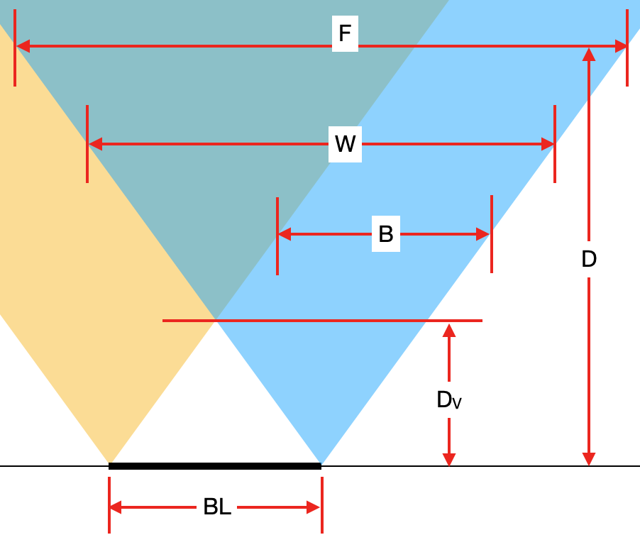 Meaning of variables on the picture:
BL [cm]- Baseline of stereo cameras.Dv [cm]- Minimum distace where both cameras see an object (thus where depth can be calculated).B [pixels]- Width of the band where depth cannot be calculated.W [pixels]- Width of mono in pixels camera or amount of horizontal pixels, also noted asHPixelsin other formulas.D [cm]- Distance from the camera plane to an object (see image Measuring real-world object dimensions).F [cm]- Width of image at the distanceD.
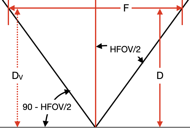 With the use of the
 tan function, the following formulas can be obtained:F = 2 * D * tan(HFOV/2)Dv = (BL/2) * tan(90 - HFOV/2)
B, we can use tan function again (same as for F), but this time we must also multiply it by the ratio between W and F in order to convert units to pixels. That gives the following formula:Python
1B = 2 * Dv * tan(HFOV/2) * W / F
2B = 2 * Dv * tan(HFOV/2) * W / (2 * D * tan(HFOV/2))
3B = W * Dv / D # pixelsHFOV of 72°, a baseline (BL) of 7.5 cm and 640x400 (400P) resolution is used, therefore W = 640 and an object is D = 100 cm away, we can calculate B in the following way:Command Line
1Dv = 7.5 / 2 * tan(90 - 72/2) = 3.75 * tan(54°) = 5.16 cm
2B = 640 * 5.16 / 100 = 33 # pixelsOAK-D-PRO will include both IR dot projector and IR LED, which will enable operation in no light.IR LED is used to illuminate the whole area (for mono/color frames), while IR dot projector is mostly for accurate disparity matching - to have good quality depth maps on blank surfaces as well. For outdoors, the IR laser dot projector is only relevant at night. For more information see the development progress here.
Measuring real-world object dimensions
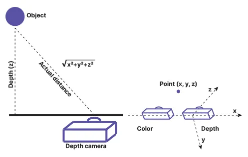 When running eg. the RGB & MobilenetSSD with spatial data example, you could calculate the distance to the detected object from XYZ coordinates (SpatialImgDetections) using the code below (after code line
 143 of the example):Python
1distance = math.sqrt(detection.spatialCoordinates.x ** 2 + detection.spatialCoordinates.y ** 2 + detection.spatialCoordinates.z ** 2) # mmNeed assistance?
Head over to Discussion Forum for technical support or any other questions you might have.