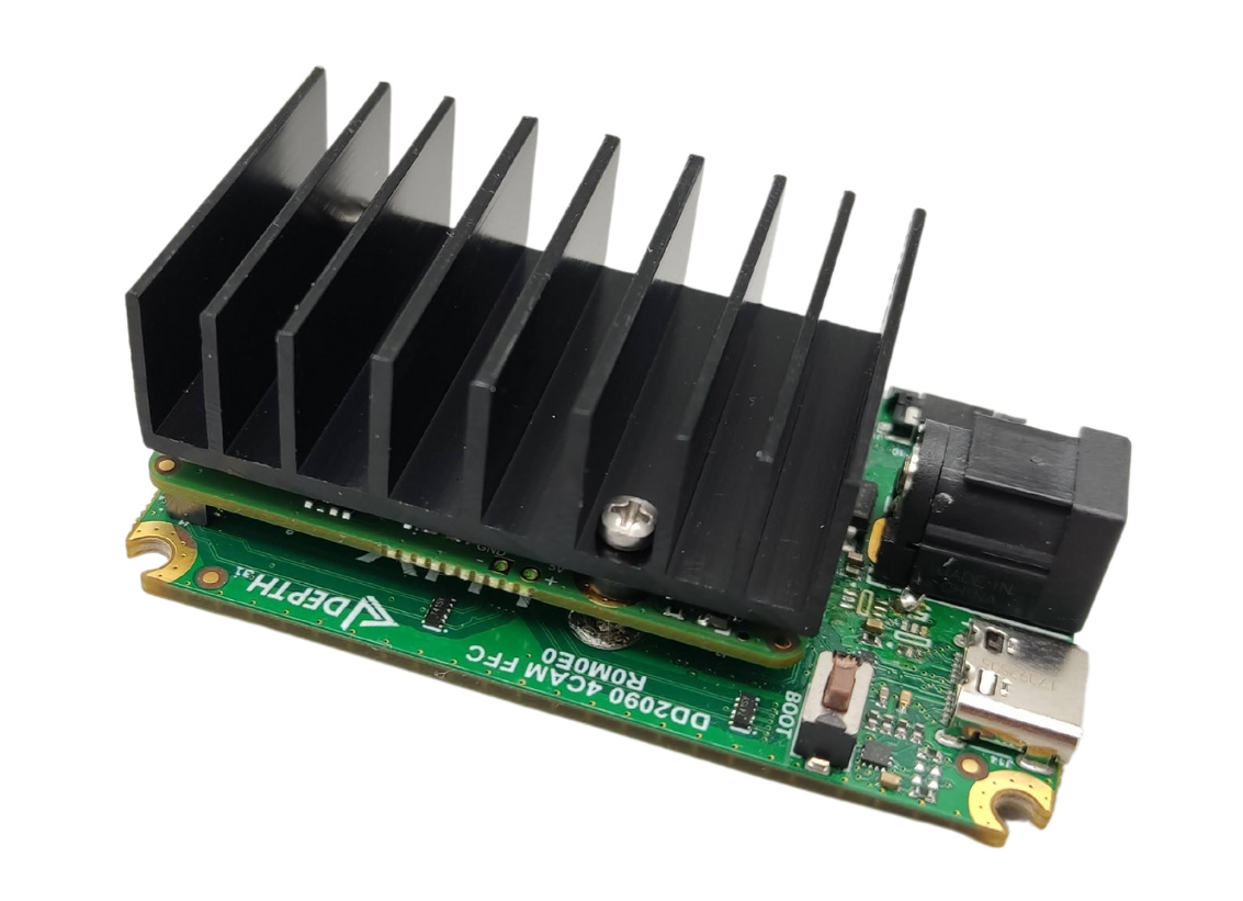
OAK-FFC-4P
Overview
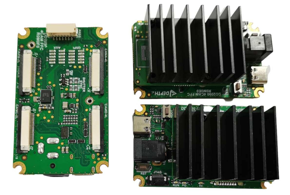
The OAK-FFC-4P (DD2090FFC) baseboard has 4 FFC interfaces which allows for:
Two 2-lane MIPI camera modules, eg. OAK-FFC-OV9282 (stereo pair)
Two 4-lane MIPI camera modules, eg. OAK-FFC-IMX378 RGB camera module, or additional OAK-FFC-OV9282 if RGB camera module is not required
Please note that only revision R1M1E1 and newer camera modules can be connected to this OAK FFC board.
To see which cameras are compatible with this OAK FFC baseboard, see the guide here: OAK FFC camera modules. Some of camera modules have a M12 mount, so you can use different lenses to get custom FoV (with wide or narrow FOV M12 lenses).
This board uses OAK-SoM-Pro and is also compatible with RPi camera interface. For that you will need a FFC from Arducam, which converts 26-pin Luxonis camera pinout to 22 pin RPi camera pinout.
In addition, IMU (over SPI) sensor is also added to this OAK FFC board.
RVC2 inside
This OAK device is built on top of the RVC2. Main features:
4 TOPS of processing power (1.4 TOPS for AI - RVC2 NN Performance)
Run any AI model, even custom-architectured/built ones - models need to be converted.
Encoding: H.264, H.265, MJPEG
Computer vision: warp/dewarp, resize, crop via ImageManip node, edge detection, feature tracking. You can also run custom CV functions
Stereo depth perception with filtering, post-processing, RGB-depth alignment, and high configurability
Object tracking: 2D and 3D tracking with ObjectTracker node
Developing with the OAK FFC
After connecting cameras to the baseboard, you can use the utilities/cam_test.py script to quickly test whether cameras are working as expected. By default, it will try to run 2x mono cameras on 2-lane mipi ports B (left) and C (right) and 2x color cameras on port A (rgb) and D (4-lane mipi ports).
If you have different cameras connected, you can specify which camera types to use with the
--cameras argument. For example, if you have 3x mono cameras connected to ports A, B, and C, you can run the following command:
python3 cam_test.py --cameras rgb,m right,m left,m
Similarly, to add such configuration into your script you can use the following code:
cam_a = pipeline.create(dai.node.MonoCamera)
cam_a.setBoardSocket(dai.CameraBoardSocket.CAM_A) # Same as CameraBoardSocket.RGB
cam_a.setResolution(dai.MonoCameraProperties.SensorResolution.THE_400_P)

cam_b = pipeline.create(dai.node.MonoCamera)
cam_b.setBoardSocket(dai.CameraBoardSocket.CAM_B) # Same as CameraBoardSocket.LEFT

cam_c = pipeline.create(dai.node.MonoCamera)
cam_c.setBoardSocket(dai.CameraBoardSocket.CAM_C) # Same as CameraBoardSocket.RIGHT

cam_d = pipeline.create(dai.node.MonoCamera)
cam_d.setBoardSocket(dai.CameraBoardSocket.CAM_D)
OAK-FFC-4P syncing
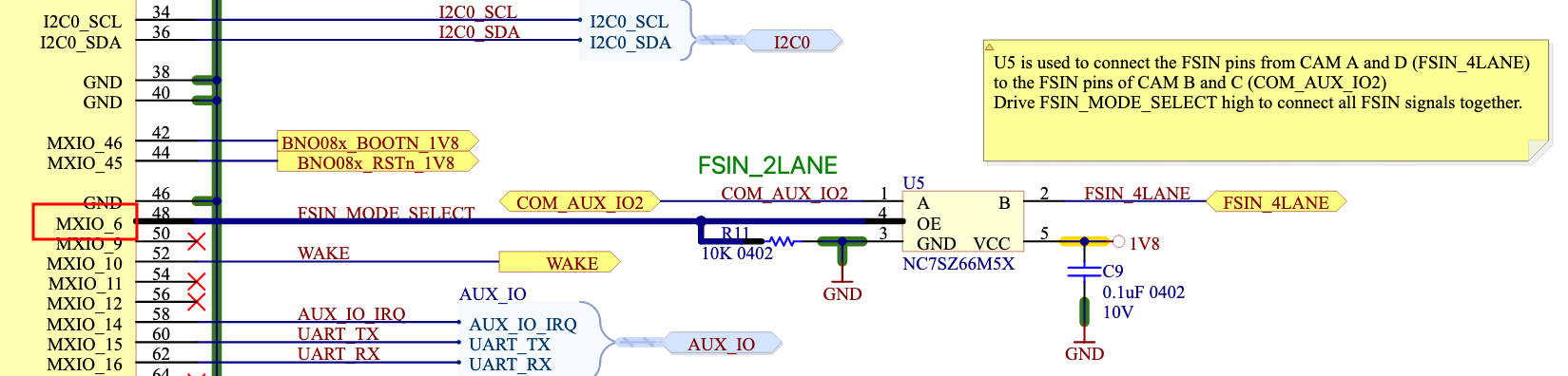
2-lane MIPI connections (CAM_B and CAM_C) have FSYNC line shorted together, and so do 4-lane MIPI connections (CAM_A and CAM_D). But if you want to enable Hardware message syncing for all 4 cameras, you need to connect the two FSYNC lines together. This can be done with the depthai API:
# OAK-FFC-4P requires driving GPIO6 high (FSIN_MODE_SELECT) to connect together
# the A+D FSIN group (4-lane pair) with the B+C group (2-lane pair)
config = dai.Device.Config()
# For FFC-4P R6 (revision 6) or higher, we changed FSIN_MODE_SELECT from GPIO6 to GPIO38!
config.board.gpio[6] = dai.BoardConfig.GPIO(dai.BoardConfig.GPIO.OUTPUT,
                                            dai.BoardConfig.GPIO.Level.HIGH)
with dai.Device(config) as device:
    device.startPipeline(pipeline)
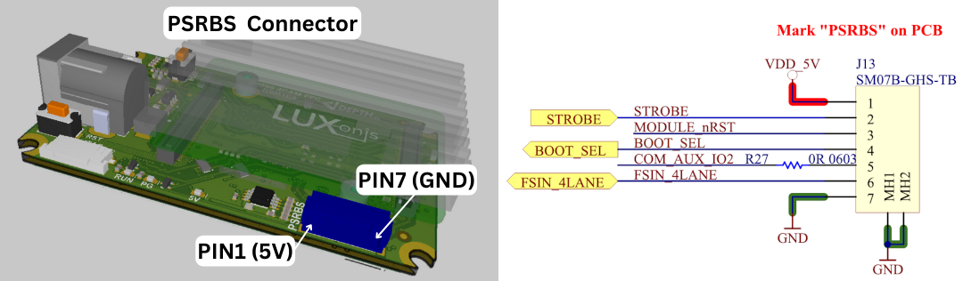
PSRBS connector
The OAK-FFC-4P has a PSRBS connector, which allows users to easily connect the OAK camera to the external logic. You can use PSRBS cable to connect to this connector.
Pin |
Name |
Description |
|---|---|---|
1 |
VDD_5V |
5V power input/output |
2 |
STROBE |
Strobe signal output, can drive external lighting (projector, illumination lights, etc.) |
3 |
MODULE_nRST |
Allows resetting the OAK-FFC from an external source (GND will reset the RVC2, same as RST button) |
4 |
BOOT_SEL |
Allows selecting whether to boot into the bootloader (1.8V will skip bootloader, same as BOOT button) |
5 |
COM_AUX_IO2 |
2-lane MIPI FSYNC signal input/output |
6 |
FSIN_4LANE |
4-lane MIPI FSYNC signal input/output |
7 |
GND |
GND power input/output |
Syncing with OAK-FFC-IR
If you have an OAK-FFC-4P R5 or newer and you wish to use the OAK-FFC-IR module, you must first configure which camera will drive the STROBE signal to the connector to which you connect your IR module. The connector located to the left of the switch (J12, see the image below).
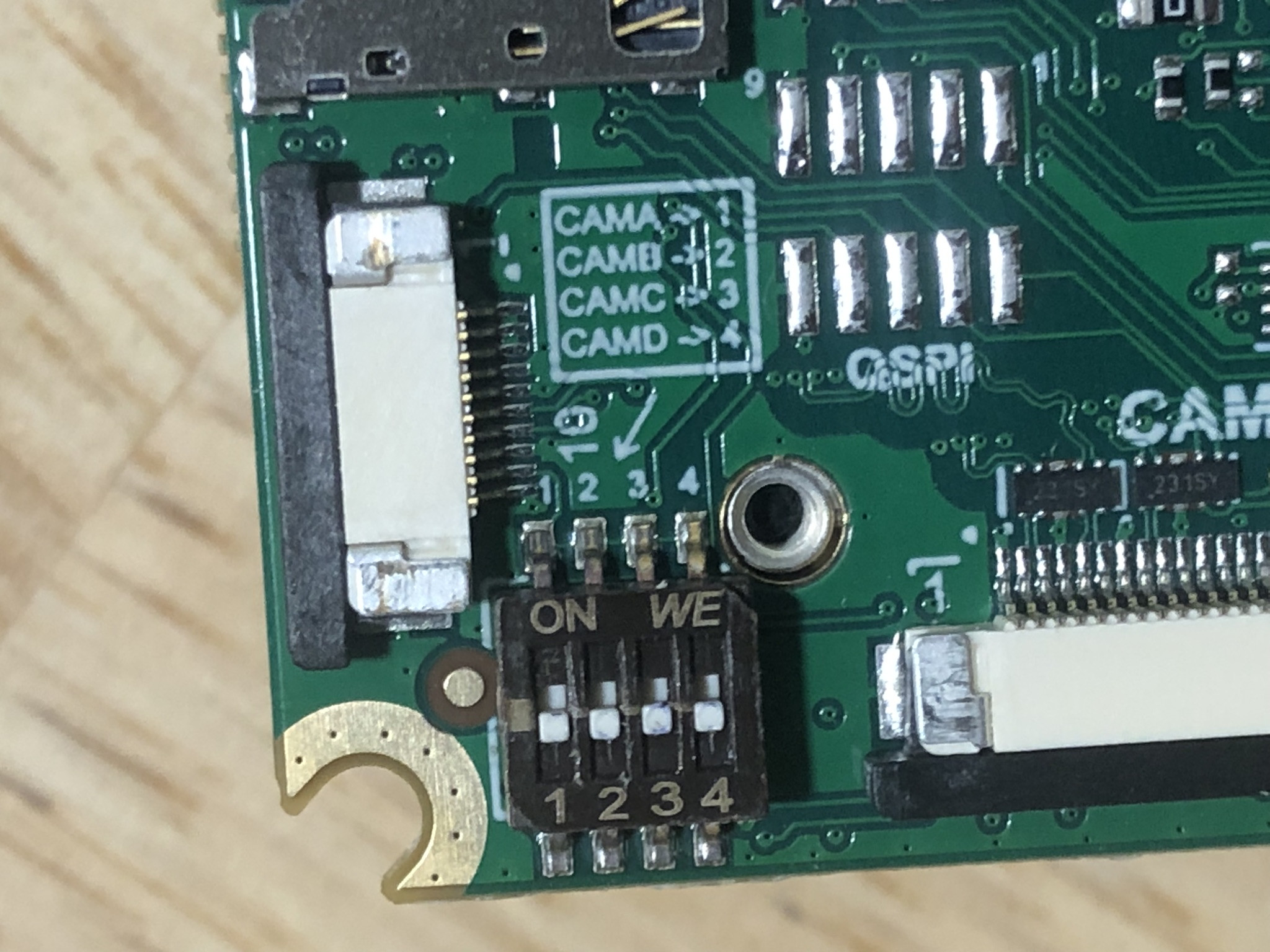
If you have stereo pair on CAM_B and CAM_C, and want to have dot projector synced with stereo pair, you should move the switch 2 or 3 up (ON). Keep in mind that only one switch can be up at a time.
Integrated IMU
This OAK camera has an integrated BNO085, a 9-axis IMU (Inertial Measurement Unit). See IMU node for the API details on how to use it.
Note: due to supply chain issues, most of the OAK camera that were manufactured between Q2 2021 and Q2 2023 have integrated BMI270 - 6-axis IMU instead.
Dimensions and Weight
Width: 62 mm
Height: 38 mm
Length: 22 mm (PCBA and heatsink)
Weight: 41g (PCBA and heatsink)

General information
2x 2-Lane MIPI interface
2x 4-Lane MIPI interface
5V power input via barrel jack
USB 3.1 Gen 1 Type-C
Interface for Luxonis OAK-SoM-Pro
Pads for OAK-SoM-Pro 1.8V SPI
Pads for OAK-SoM-Pro 3.3V SDIO
Pads for OAK-SoM-Pro 1.8V Aux Signals (I2C, UART, GPIO)
5V Fan OR USB Type-C
Design files produced with Altium Designer 20
Minimal and maximal perceiving distances of the camera
Minimal depth perceiving distance of the camera depends on mono camera FOV, resolution, baseline and stereo depth mode, more info is available on the Stereo Depth documentation.
Since this device has modular mono cameras, you can choose a custom stereo baseline (depending on how it is set up). When using OAK-FFC-OV9282, the formulas for min/max depth perceiving distances are:
Min distance (800P) =
882.5 * baseline / 95Min distance (400P) =
441.25 * baseline / 95Min distance with extended disparity (800P) =
882.5 * baseline / 190Min distance with extended disparity (400P) =
max(441.25 * baseline / 190, 19.6)Max perceivable distance (using subpixel) =
baseline/2 * tan((90 - 71.9/1280) * PI/180)
For more information about the maximum distance see the Stereo Depth documentation.
Power consumption
Most of the power is consumed by the RVC2, so the power consumption mostly depends on the workload of the VPU:
Base consumption + camera streaming: 2.5W - 3W
AI subsystem consumption: Up to 1W
Stereo depth pipeline subsystem: Up to 0.5W
Video Encoder subsystem: Up to 0.5W
So the total power consumption can be up to ~5W if you are using all the features at 100% at the same time. To reduce the power consumption, you can reduce FPS of the whole pipeline - that way, subsystems won’t be utilized at 100% and will consume less power.
Operating temperature
The ambient operating temperature of RVC2 based devices is between -20°C and 50°C when fully utilizing the VPU.
Similarly to the Power consumption, max operating temperature depends on VPU utilization. The higher the VPU utilization, the more heat the VPU will generate. The RVC2 VPU can continuously operate at 105 °C, after which the depthai library will automatically shut down the device (to avoid chip damage).
To find out more, see our Operative temperature range documentation.
Getting started
The OAK-FFC-4P is powered via USB Type-C or from a 5V, 5.5m x 2.5mm barrel jack, and interfaces to a host via USB 3.1 Gen1 Type-C. With cameras and the OAK-SoM-Pro, total power consumption usually stays below the 900ma specification of USB 3, but Type-C power of 1.5A or greater is recommended.
Interfacing with the OAK-SoM-Pro is also possible with OAK-FFC-4P connector pads J3, J4, and J5. These pads are designed for the Amphenol/FCI 20021121-00010T1LF or equivalent. Please refer to the schematics for pinout information.
The reset button resets the OAK-SoM-Pro only. The boot button overrides boot mode to USB boot if different boot mode is set on the NOR Flash.
The 5V LED indicates 5V power is present on the board. The PG LED indicates “power good” from the OAK-SoM-Pro. The “RUN” LED indicates that the OAK-SoM-Pro is not in reset.
FFC cables
For FFC cables we use Molex series 15166. Along with the OAK FFC board, we ship 26 pin count, same-sided, 152mm cables (part number 151660281). If you would like to use shorter/longer FFC cables, you can get them here.